26Sp-Microclimate-OutdoorPlus
UMCF
A collection of components to use the
urbanMicroclimateFoam solver.
A Grasshopper plugin for microclimate simulations
The plugin is based on the urbanMicroclimateFoam open-source solver based on OpenFOAM,
developed by the Chair of Building Physics at ETH Zürich.
- GitHub repository: https://github.com/OpenFOAM-BuildingPhysics/urbanMicroclimateFoam
Overview
urbanMicroclimateFoam (uMFoam) is an open-source solver built on OpenFOAM for modeling urban microclimates.
It simulates multiple coupled physical processes, including:
- Turbulent airflow
- Heat and moisture transport in air
- Radiative heat exchange (shortwave and longwave)
- Heat and moisture storage in building materials (HAM model)
- Urban vegetation heat balance
Learn more at the official repository:
🔗 urbanMicroclimateFoam GitHub
Key Features
🌊 CFD — Computational Fluid Dynamics Model
- Solves turbulent, convective airflow
- Handles heat and moisture transport in the air subdomain
🏗️ HAM — Heat and Moisture Transport Model
- Manages absorption and transport
- Controls storage of heat and moisture in porous building materials
☀️ RAD — Radiation Model
- Calculates net longwave and shortwave radiative heat fluxes
- Uses view factor approach
🌳 VEG — Vegetation Model
- Solves heat balance for urban trees
- Handles green surfaces
Prerequisites
1. Install OpenFOAM (Windows)
Install blueCFD-Core 2020, which includes OpenFOAM 8.
- Download:
blueCFD-Core-2020-1-win64-setup.exe
2. Install UMCF Plugin for Grasshopper (Rhino)
- Open Rhinoceros
- Run the
PackageManagercommand - Search for UMCF
- Enable “Include pre-releases”
- Click Install and restart Rhino
Spring 2026 Additions: Wind Flow and Urban Heat Island in Residential Morphology
Tokyo Case Study
Overview
This project explores the relationship between urban geometry and microclimate in Tokyo through computational simulation workflows using Rhino, Grasshopper, and CFD-based environmental analysis. Focusing on the dense urban fabric of central Tokyo, the project investigates how different building configurations influence airflow, heat accumulation, and pedestrian-level environmental conditions. The workflow combines urban massing generation, geometric processing, and environmental simulation to analyze the spatial behavior of wind and thermal performance within high-density city blocks. By integrating computational design methods with environmental analysis, the project aims to better understand how urban form shapes microclimatic conditions in contemporary cities. The project also serves as an experiment in connecting architectural geometry workflows with simulation pipelines, particularly through the use of Grasshopper-based procedural systems and volumetric environmental visualization.
Motivation
Tokyo presents a unique urban condition characterized by extreme density, narrow street networks, heterogeneous building scales, and complex airflow environments. While many studies evaluate environmental performance at large urban scales, this project focuses on the spatial and experiential scale of the city block.
Challenge
- Preparing geometry for simulation
One of the most difficult aspects of the project was preparing urban geometry for CFD simulation. While the original building models were generated procedurally in Grasshopper, simulation workflows required clean, watertight, and computationally efficient meshes.
Architectural geometry that visually appeared correct often produced unstable or failed simulation results due to:
- non-manifold edges
- duplicated faces
- open meshes
- overlapping geometry
- inconsistent normals
- excessively dense topology
This revealed a major difference between architectural modeling workflows and simulation-ready geometry preparation.
- Meshing workflow and topology problems
A significant portion of the project involved experimenting with different meshing strategies to generate stable and optimized simulation geometry.
TriRemesh was initially used to simplify and regularize the urban geometry. The goal was to:
- reduce irregular topology
- create cleaner triangulated surfaces
- improve mesh consistency before simulation
However, several issues emerged:
- excessive simplification distorted building edges
- important geometric details were lost
- mesh density became inconsistent across the model
- some meshes still contained non-manifold conditions
Balancing geometric accuracy and computational efficiency became a constant challenge.
Gmsh integration was also tested for CFD preparation. Gmsh provided:
- more control over mesh resolution
- better volumetric meshing
- improved compatibility with simulation pipelines
However, integrating Gmsh into the workflow introduced additional complexity:
- geometry export compatibility issues
- failed mesh generation
- unstable volumetric meshes
- difficulties controlling element density near dense urban regions
In many cases, small geometric imperfections caused the meshing process to completely fail, requiring repeated geometry cleanup and reconstruction.
- Difference between test runs and the final run
Before conducting the final simulation, numerous test runs were performed throughout the project. During the test run phase, smaller simulations were used to evaluate:
- geometry validity
- mesh stability
- airflow behavior
- voxel resolution
- solver setup
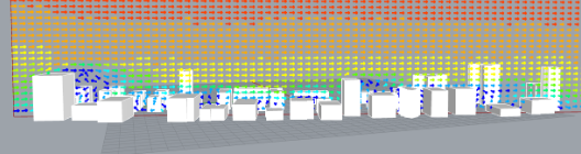
These test simulations operated relatively successfully and produced stable airflow visualizations and scalar field outputs around the urban geometry. In particular, the simulations were able to reveal airflow stagnation zones and circulation patterns generated by dense building configurations, demonstrating the overall viability of the workflow.
However, during the final actual run, issues emerged related to the terrain mesh. The terrain geometry contained problematic mesh conditions that caused instability within the standard eddy3D workflow. As a result, the solver had to be executed manually rather than through the normal automated pipeline. During this manual process, the normalization stage failed to function properly. In order to complete the simulation, normalization ultimately had to be turned off. Although this allowed the simulation to run, the resulting environmental data was no longer properly normalized, which led to inaccuracies in the final results.
This particularly affected:
- the reliability of airflow scalar values
- quantitative comparison between regions
- the evaluation of environmental intensity
Future Improvement
A major future improvement is to automate the geometry screening process in Grasshopper in order to generate simulation-ready geometry more efficiently. In this project, many simulation issues were caused by geometry and mesh conditions, especially in the terrain model. Therefore, future development should focus on building a Grasshopper-based warning and validation system that can detect problematic geometry before running the simulation.
This system could automatically check for issues such as:
- open meshes
- non-manifold edges
- duplicated faces
- overlapping geometry
- extremely small mesh faces
- inconsistent normals
- terrain discontinuities
- excessive mesh density
By identifying these problems earlier in the workflow, the simulation setup could become more stable and less dependent on manual troubleshooting. The goal is to create a more reliable preprocessing pipeline where Grasshopper not only generates geometry, but also evaluates whether that geometry is suitable for CFD simulation. This would reduce failed runs, improve mesh stability, and make it easier to produce accurate simulation results.
Mumbai Case Study
Overview
This case study evaluates how residential urban morphology in Mumbai, India, influences wind patterns and the urban heat island (UHI) effect. Using FluidX3D for wind simulation, the study investigates how building geometry and orientation within dense residential environments affect microclimate behavior, while also documenting the technical boundaries of the simulation workflow.
Motivation
Mumbai's residential neighborhoods are defined by high building density, varied building heights, and often with dense vegetation interspersed throughout. These tightly packed residential clusters frequently sit alongside more openly spaced commercial or mixed-use buildings, creating a range of density conditions that further shape local wind flow and heat retention. This study aims to understand those physical interactions, while also identifying where the current simulation tool, FluidX3D, reaches its limits in capturing the full complexity of such environments, particularly where vegetation and overlapping or touching geometries are concerned.
Central Idea
Building placement and geometric configuration are treated as the primary drivers of wind-driven microclimate variation. By constructing 3D models of selected Mumbai residential blocks and running iterative wind simulations, the project assesses how spatial arrangements respond to different incident wind directions, and what barriers prevent the inclusion of vegetation in this type of analysis.
Methodology
1. Geometry Preparation and Urban Morphology Modeling
Building footprints for residential areas including Rebello Road and Mumbai Coastal Road were imported into Rhinoceros/Grasshopper via OpenStreetMap (OSM) Buildings. The raw geometries required significant preprocessing: the ground plane was flattened to seat all structures on a common base level, and building heights were manually verified and adjusted to match real-world conditions.
2. Simulation Setup and Wind Analysis
A regional coastal weather file was used as a proxy for localized inland atmospheric boundary conditions. Simulations were run iteratively to visualize wind-building interactions. To examine changes in wind velocity and direction throughout the building, vertical planes were inserted at different locations. However, generating stable sampling points on these vertical planes proved inconsistent: points created in an initial static run would often fail to regenerate after moving the plane or when switching to the animated simulation.
Challenges
- Geometry Overlaps and Extreme Proximity: Simulations failed when building footprints overlapped or sat in extreme proximity. This limitation is significant when attempting to model Mumbai's densest residential settlements, where minimal setbacks are common.
- Vegetation Integration: FluidX3D does not support vegetation meshes currently, preventing analysis of tree cover or green infrastructure as a UHI mitigation factor within this workflow.
- Vertical Plane Point Generation: Technical instability in generating analysis points on vertical planes disrupted the height-based wind assessment. Points could appear in one run but disappear after moving the plane or animating the simulation, and the issue could not be fully resolved yet.
Future Improvements
Potential directions for future work include:
- Developing automated scripts to detect and correct overlapping building footprints, enabling higher-density simulations without manual intervention.
- Investigating stable methods for generating and retaining sample points on dynamic vertical planes within the FluidX3D/Grasshopper interface.
Street Canyon Case Study
Overview
This project investigates the relationship between street canyon geometry and urban microclimate through computational simulation workflows using Rhino, Grasshopper, and eddy3D-based CFD environmental analysis. Focusing on dense urban conditions in major U.S. cities, particularly New York City, the project explores how different street canyon configurations influence airflow behavior, pedestrian comfort, and environmental conditions at the street level. The workflow combines urban geometry extraction, procedural modeling, and environmental simulation to analyze the spatial effects of balconies, vegetation, building height variation, narrow street corridors, and other urban features on microclimatic performance. By integrating computational design workflows with CFD simulation, the project aims to better understand how urban morphology impacts environmental comfort within dense city environments.
Motivation
Dense urban environments create complex airflow conditions that strongly affect pedestrian comfort, ventilation, and thermal experience at street level. Street canyons, especially in cities with high pedestrian density such as New York City, present unique environmental challenges due to narrow streets, repetitive building masses, and limited airflow circulation. While many environmental studies focus on large urban scales, this project examines the experiential scale of individual city blocks and street corridors. The research also investigates how computational simulation tools such as eddy3D can assist architects and urban planners in evaluating urban design strategies that improve environmental quality for pedestrians and residents.
Challenge
- Preparing Geometry for Simulation
One of the primary challenges involved preparing urban geometry for CFD simulation. Building and street canyon models were extracted and generated through Rhino and Grasshopper workflows using geographic coordinates from Google Earth. Although the geometry appeared visually correct, many models produced unstable simulation behavior due to issues within the mesh topology and preprocessing pipeline.
Several problems emerged throughout the workflow, including:
- problematic polysurface conditions
- mesh instability during preprocessing
- geometry logs crashing during mesh checks
- inconsistent mesh preparation
- difficulties solving vegetation and solid building regions
These issues revealed the significant gap between architectural modeling workflows and simulation-ready computational geometry.
- Meshing Workflow and Simulation Problems
A substantial portion of the project focused on debugging and optimizing the meshing workflow required for eddy3D simulations.
The project experimented with:
- Gmsh-based meshing workflows
- remeshing during simulation
- preprocessing geometry cleanup
Gmsh offered more control over volumetric mesh generation, but also introduced additional complexity. Several simulation runs failed because the geometry log crashed during the mesh checking stage. In some cases, remeshing operations during simulation may not have functioned correctly, causing instability within the solver pipeline. Additional issues appeared in faceAgglomerate preparation and preprocessing steps, preventing the simulation from advancing successfully.
- Difference Between Test Runs and Final Simulation
Before conducting the final simulation, multiple test runs were performed throughout the project. These smaller simulations were used to evaluate:
- geometry validity
- mesh stability
- airflow behavior
- preprocessing compatibility
- simulation setup reliability
During testing, simulations successfully generated airflow visualizations and demonstrated circulation patterns around dense urban geometry. In particular, the simulations revealed airflow stagnation zones and circulation behavior caused by narrow street canyons and repetitive building configurations, confirming the overall viability of the workflow.
However, during the final simulation runs, issues emerged related to geometry instability and mesh processing. Simulations initially solved vegetation regions successfully, but crashed shortly after calculations began for solid building regions. Additional problems within preprocessing and mesh preparation prevented stable simulation execution.
These issues particularly affected:
- simulation reliability
- mesh consistency
- solver stability
- environmental data accuracy
- quantitative comparison between urban regions
Future Improvement
A major future improvement is to automate geometry validation and mesh quality analysis directly within Grasshopper before simulations begin. Much of the instability encountered throughout the project resulted from problematic geometry conditions that were difficult to identify manually.
Future development could include a Grasshopper-based validation system capable of automatically detecting:
- problematic polysurfaces
- open meshes
- non-manifold edges
- overlapping geometry
- failed mesh regions
- inconsistent normals
- excessive mesh density
- terrain and geometry discontinuities
By integrating automated geometry screening into the procedural modeling workflow, future simulations could become significantly more stable and efficient. The goal is to create a computational preprocessing pipeline where Grasshopper not only generates urban geometry, but also evaluates whether the geometry is suitable for CFD simulation before exporting to eddy3D or Gmsh workflows. This would reduce failed simulations, minimize manual troubleshooting, and improve the reliability of environmental analysis results for dense urban street canyon studies.
Presentation